GIBO Sensor Faucet Control Module Product Specification
Product specification for the GIBO remote-controlled infrared sensor faucet control module. The fourth-generation GIBO i

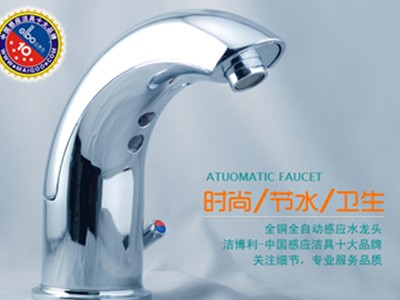
GIBO Sensor Faucet
Product Specification Sheet for Remote-Controlled Infrared Control Module
Sensor Faucet Functional Description:
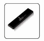
GIBO’s fourth-generation infrared control module for sensor faucets features an imported MCU and advanced 0402 SMT surface-mount technology, offering a compact design suitable for standard sensor faucets, basin taps, wave-sensor models, and instant-activation units. All GIBO sensor faucet products utilize the proprietary Liteon sensing technology for rapid response and false-trigger prevention. Built-in ultra-low-power technology reduces standby current to as low as 25 µA, extending battery life beyond 18 months with four AA batteries. The module employs a robust anti-interference algorithm, validated through tests against 20 light sources and 17 common household appliances, ensuring superior reliability and performance.
Sensor Faucets operate on infrared reflection technology. When a hand enters the sensor zone, the emitted infrared beam is reflected off the skin to the receiver. A microcontroller processes this signal and activates a pulse solenoid valve to open the flow. Once the hand leaves the detection range, the valve automatically closes via an internal spring reset. As touchless water-saving fixtures that require no manual operation, Sensor Faucets effectively prevent cross-contamination, making them ideal for high-traffic public areas such as schools, train stations, airports, and bus terminals.
l Product Appearance Schematic
Installation Dimension Diagram
|  |

l Key Technical Parameters:
Dimensions: 15 (W) × 24 (L) × 10 (H)
l Operating Voltage: DC 4.5–6.4V
Power consumption: Standby power ≤ 0.15 mW (≤ 25 µA).
Default factory-set sensor detection distance: 280 mm for sensor faucets. Adjustable range: 100–450 mm (reference target: 297 mm × 297 mm standard white board). Detection distance tolerance: within ±10% of the rated distance.
l Output: Maximum output current 800 mA, output voltage 4.2 V–6 V, output pulse width 35 ms.
Low-voltage alarm: The unit enters low-voltage alarm mode when the operating voltage is ≤4.5±0.1 V.
l Distance Stability: With supply voltage dropping from 6.4 V to 4.5 V, distance variation remains within ±5%; with temperature rising from −20 °C to +60 °C, distance variation remains within ±15%.
l Service life: ≥500,000 cycles
l Environmental Adaptability
(1) Operating temperature: -20°C to 60°C
(2) Storage temperature: 0°C–50°C
(3) Relative humidity: 10%–95%
(4) Atmospheric pressure: 86–106 kPa
l Anti-interference
⑴ Multiple sensor faucets can operate simultaneously without any false triggering.
⑵ No false activation caused by interference from common electrical appliances.
(3) When illuminated at an angle from more than 1 meter away by incandescent lamps or T5 fluorescent lights, the variation in detection range shall be less than ±10%.
l Vibration Resistance: Amplitude 0.35 mm, Frequency 10–55 Hz, Three Mutually Perpendicular Directions, 10 Sweep Cycles; Appearance and Performance Meet Requirements
Impact Resistance: Do not strike or hit
Installation Environment: The controller should be installed away from direct sunlight and mirror reflections.
l Features & Description:
Water starts automatically when hands enter the sensor range (256 ms response time), with one indicator light flash, and stops when hands leave (1.2–1.8 s response time). To prevent false triggering from obstacles within the detection zone, water flow is automatically cut off after 60 seconds of continuous operation.
Remote Sensing Distance Adjustment: Operate within 0.3–1 m directly in front of the sensor faucet controller. The remote control indicator light turns on when a button is pressed (keep the remote aligned with the controller until the light turns off before making further adjustments). Press “1” to extend the sensing distance by 2–3 cm per press; press “2” to shorten it by 2–3 cm per press. When the maximum or minimum range is reached, the indicator flashes at 1 Hz for 3 seconds. Adjusted settings are stored in the internal chip and retained after power loss, requiring no reconfiguration upon restart.
1. Smart Sensing: Features Liteon sensing technology for ultra-fast response. Water flows instantly when hands enter the detection range and stops immediately upon exit, with a on/off response time of <0.5s.
2. Ultra-compact circuit design: Microcomputer-based smart control for intelligent power saving, with static power consumption ≤ 25 µA controlled by microchip
3. Hygienic & Convenient: Touchless sensor activation—water flows instantly when hands are detected and stops automatically when they leave. This contact-free operation effectively prevents the spread of bacteria and cross-infection.
4. Timeout Protection: If the sensor faucet operates continuously for more than 1 minute, it will automatically shut off to prevent water waste caused by prolonged flow due to objects remaining within the detection zone. Water resumes upon renewed detection.
5. Automatic Sensing Distance Adjustment: The infrared sensor controller is powered by a microcomputer MCU, enabling the optimal sensing range to be set according to the usage environment.
6. Smart Power Saving: Features GIBO Liteon Sensor Technology with a low-power chip controller and built-in energy-saving mode for ultra-low power consumption and greater efficiency (DC typeProductsPowered by 4 AA alkaline batteries, with a standby current of ≤25 μA. Under typical use of 200 cycles per day, battery life reaches up to 18 months.
7. Low Battery Alert: When battery voltage drops below 4.6V, the red indicator light flashes to signal that the batteries need replacement.
8. Power Supply Options: AC (220V), DC (standard AA alkaline batteries), or AC/DC dual mode. The AC/DC dual mode supports automatic soft switching.

l Test Environment and Equipment:
Unless otherwise specified, all tests and inspections for sensor faucets shall be conducted under normal room temperature conditions.
l Instruments Required for Sensor Sanitary Ware Testing
Sensor Sanitary Ware Distance Test Rig (for Distance Testing)
Multimeter (for static power consumption testing)
Regulated Power Supply (for power supply, low-voltage alarm testing, and distance stability testing)
Solenoid valve or other load (for sensor load-capability testing)
Incandescent or fluorescent lamp (for light resistance testing)
l Reference standards for testing and acceptance of sensor-operated sanitary ware products are listed in the table below
Test Item | Test Method & Instrumentation | Standard Requirements |
Appearance | Visual Inspection | No obvious scratches on mirror finish; no visible adhesive residue on other parts |
Sensing Distance | Tested using a test bench. Standard factory setting: 280mm for faucets (reference object: 29.7cm x 29.7cm standard white board) | Sensing distance error within ±10% of rated distance (factory settings may vary based on sensor faucet design) |
Static Power Consumption | Multimeter connected in series with the power supply | Static power consumption ≤0.15mW (≤25µA) |
Low Voltage Alarm | Using a regulated power supply, gradually reduce voltage from 6V to 4.4V | Upon detecting an object, indicator LED flashes at 2Hz frequency; controller output is disabled |
Distance Stability | Using a regulated power supply, gradually reduce voltage from 6V to 5.5V, 5V, and 4.5V; measure and record distance on test bench at each step | When supply voltage drops from 6.4V to 4.5V, distance variation does not exceed ±5% |
Ambient Light Resistance | Irradiated diagonally by a 100W incandescent bulb placed >1m away on the test bench | Distance variation less than ±10% |
Load Capacity & Functional Test | Input voltage 4.5V; tested on water flow rig using actual solenoid valves at 8kg pressure (0.8MPa) | Operates normally |
Anti-Interference Capability | Multiple units operating simultaneously or common electrical appliances used nearby | No false triggering |