GIBO Toilet Sensor Installation Guide
GIBO Toilet Sensor Installation Guide. GIBO Squat Pan Sensor Installation Dimensions Diagram: Installation Steps for the
GIBO Toilet Sensor Installation Guide
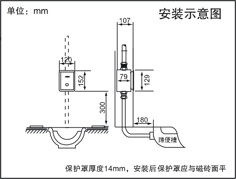
GIBO Squat Pan Sensor Installation Dimensions Diagram:

Squat Pan Sensor Installation Steps
(1) Select the installation location and chisel out a recess for the squat pan sensor mounting box.
Select the installation location based on the mounting dimension drawing, cut the recess, embed the water supply piping, and flush the supply lines. The recess depth shall be no less than 105 mm as shown in Figure 1; the dashed area indicates the channel for routing the power supply line.

Pre-Installation Notes:
a. Do not install the sensor directly opposite reflective surfaces (e.g., mirrors, polished stainless steel panels, or other mirror-finish objects).
b. Do not install where direct or reflected sunlight enters the sensor window.
c. Do not install near sources of intense UV radiation or electromagnetic fields.
d. Flush the water supply lines thoroughly before installation.
e. Ensure the main water supply pipe for the toilet sensor is larger than DN32.
(2) Connect the water supply and power lines to the fixed recessed box
Place the sensor recessed box into the slot, secure it level and aligned using wooden blocks (spacer blocks), and connect the water supply pipes. Tighten the outlet nuts (outlet pipe connections vary by squat pan model—follow the installation dimension diagram). Note: Flush the water supply lines thoroughly before installing this product.
For AC-powered sensor-operated squat pan products, remove the protective cover, route the power cable into the recessed box, connect the AC Power Box, and reinstall the cover (ensure proper insulation of the power connector terminals).

Important Notes:
A. The sensor’s mounting position directly affects its performance; therefore, verify the position by measurement after placement and fix it only once accuracy is confirmed.
B. Do not reverse the inlet and outlet directions.
C. Do not lose the rubber sealing washers for pipe connections.
D. Do not allow the connector to become damp.
E. The center of the pre-embedded box for the Squat Pan sensor must be aligned with the center of the Ceramic Squat Pan and kept parallel to the wall; otherwise, false triggering may occur. When installing three or more Sensor Touchless units in a single Public Restroom, it is recommended that the inner diameter of the main water supply pipe exceeds 38 mm.
F. Do not connect the DC output of the power adapter to an AC mains supply.
G. Do not power the AC adapter during installation. It is recommended that the mains supply cable use conductors with a nominal cross-sectional area of ≥0.5 mm².
(3) Water Test and Wall Installation
Once the concealed box is securely installed, connect the water supply and perform a pressure test. After confirming that all pipe connections are leak-free, fill the gaps around the valve box with mortar. Proceed with wall finishing in accordance with the installation protection cover instructions, ensuring the tile surface remains parallel to the end face of the cover.

Installation Protection Cover Instructions:
☆ After plumbing and electrical installation, secure the pre-embedded cover for the squat pan sensor with screws.
☆ Cement mortar and tile installation must follow the illustrated requirements: A) The tile surface must not exceed the opening of the sensor faucet’s protective cover; B) Tiles must be flush against the edge of the protective cover. (If warning labels are present, adhere to their instructions.)
☆ After wall finishing is complete, remove the protective cover from the sensor sanitary ware and install the toilet sensor panel assembly for commissioning.
(4) Installation and Connection of Sensor Sanitary Ware Panels
Remove the construction protection cover from the flushometer recessed box for the squat pan. Take out the sensor panel assembly, unscrew the 2.5mm screws at the bottom of the stainless steel sensor panel, and remove the mounting base. Connect the power cable of the sensor module to the DC output of the power adapter (or battery) inside the recessed box, and connect the signal terminal to the solenoid valve signal terminal in the recessed box. Secure the mounting base to the recessed box using the supplied installation screws. Snap the stainless steel panel onto the base and fasten it with the 2.5mm screws to complete the installation.

(5) Squat Pan Sensor Installation Diagram

These installation instructions apply to GIBO concealed sensor squat pan flush valves with a recessed mounting dimension of 80 mm × 160 mm.